
Click here for English version
Wie baue ich mir einen HomeMatic Schaltaktor?
- Arduino Nano, CC1101 und ein Relais Board kaufen
- Bauteile mit Steckverbindern verdrahten oder verlöten
- AsksinPP Library aufspielen
- Mit FHEM oder HomeMatic CCU pairen
Motivation
Ein HomeMatic Schaltaktor bildet das Gegenstück zum CUL 868 und läßt sich genauso günstig und einfach bauen. Der Schaltaktor unterstützt eine AES Verschlüsselung. Es gibt verschiedene Sketche, die auf den Schaltaktor geladen werden können. Auf das Modul können zum Beispiel vier 5V Relais zum Schalten von 220V angeschlossen werden.
Ich habe schon etliche von den Schaltaktoren gebaut und inzwischen eine kleine Platine in China erstellen lassen, mit der der Aufbau deutlich schneller geht. Wer daran Interesse hat, kann mich gerne kontaktieren.

Materialliste
Bei dem Arduino ist wieder darauf zu achten, daß er einen echten FTDI Chip hat um Ärger zu vermeiden und keinen CH340. Wenn man mehrere dieser Schaltaktoren baut, kann kan auch Pro Minis kaufen und diese mit einem Programmer flashen.
Bauteil
Arduino Nano FT232RL mit USB Kabel (Amazon, Aliexpress)*
CC1101 868 Mhz (Amazon, Aliexpress)*
Relais Board
(Hinweis: Als Amazon-Partner verdiene ich an qualifizierten Verkäufen.)
Verdrahtung
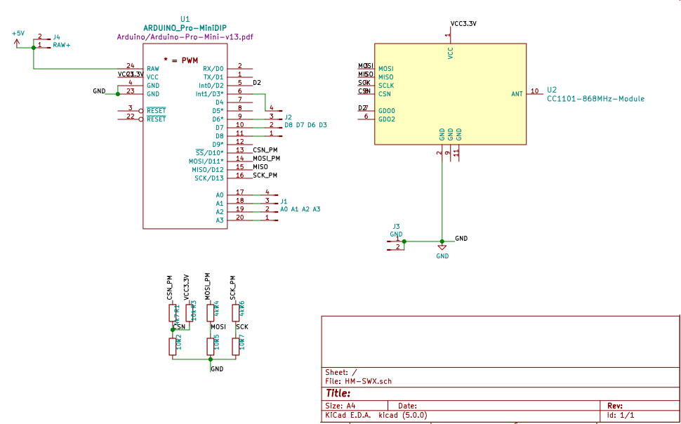
Die Verdrahtung ist wie folgt vorzunehmen.
| Arduino | CC1101 |
| VCC 3.3v | VDD |
| PIN GND | GND |
| nicht verbunden | GDO2 |
| PIN D02 | GDO0 |
| PIN D10 | CSn (SS) (ggfs über 4k7 Widerstand mit 10k gegen GND) |
| PIN D11 | SI (MOSI) (ggfs über 4k7 Widerstand mit 10k gegen GND) |
| PIN D12 | SO (MISO) |
| PIN D13 | SCK (ggfs über 4k7 Widerstand mit 10k gegen GND) |
Wer den CC1101 schonen möchte, kann auch Widerstände einbauen um vom 5V Niveau auf 3.3V zu konvertieren. Dazu verwendet man 10k und 4k7 Widerstände. Die Alternative ist einen 3.3v Arduino zu verwenden, so haben Arduino und CC1101 das gleiche Spannungsniveau. Anbei noch der Schaltplan zur Verdeutlichung.
Software
Für den vierfach Schaltaktor nutze ich AsksinPP die man als Library in den Arduino einbindet. Mir gefällt an AsksinPP insbesondere die Verschlüsselung. Wie wir die Verschlüsselung AES aktivieren, zeige ich Euch in einem weiteren Artikel.
Es sind etliche Beispiele in der Library enthalten, deswegen konzentrieren wir uns auf den vierfach Schaltaktor und editieren das File HM-LC-SWX-SM.
Device ID und Serial
Wir suchen die folgende Stelle in dem relativ kurzem Code.
// define all device properties
const struct DeviceInfo PROGMEM devinfo = {
{0x12,0x34,0x56}, // Device ID
"papa000000", // Device Serial
{HM_LC_SW4_SM}, // Device Model
0x16, // Firmware Version
as::DeviceType::Switch, // Device Type
{0x01,0x00} // Info Bytes
};
Definiert Eure eigene
{0x12,0x34,0x56}, // Device IDsowie Eure
"papa000000", // Device Serial
Relais Ausgänge
Als letztes definieren wir noch unsere Relais Ausgänge oder merken sie uns einfach. An diese Ausgänge können wir unser Relais Breakout Board anschliessen.
#define RELAY1_PIN 5
#define RELAY2_PIN 6
#define RELAY3_PIN 7
#define RELAY4_PIN 3
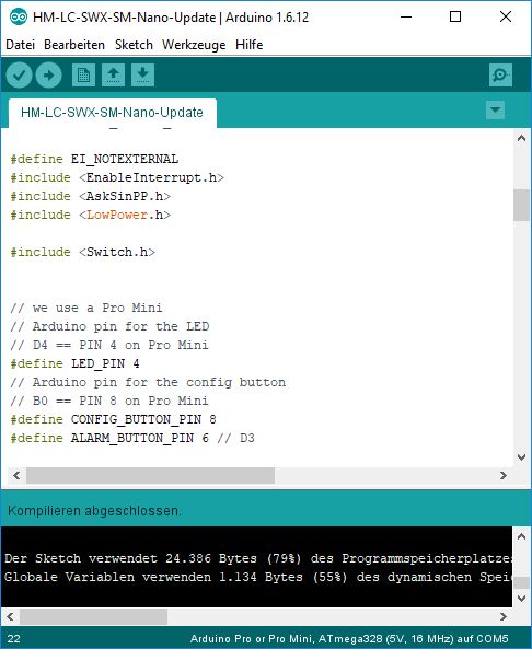
Software aufspielen
Nun sind wir auch schon soweit um den Code zu kompilieren und hochzuladen. Wir verbinden unseren Arduino mit dem PC und achten auf den richtigen COM Port. Dann kompilieren wir die Software und laden sie auf den Arduino.
Pairing
Im Prinzip können wir den Schaltaktor mit einer Homematic CCU pairen. In meinem Fall pairen wir es mit FHEM. Dazu wechseln wir zu unserem FHEM Frontend. Wir geben in das Kommandofeld
attr CUL1 hmPairForSec 600

ein um den CUL in den Pairing Modus zu versetzen.
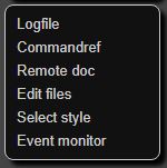
Jetzt haben wir 10 Minuten Zeit unseren Schaltaktor zu pairen. Wir öffnen den Serial Monitor des Arduinos mit 57600 Baud und den Event Monitor (ganz unten links) von FHEM.
Dann verbinden wir PIN8 des Arduinos ca. 5 Sekunden mit GND. Ihr müsstet nun die Kommunikation zwischen dem CUL und dem Schaltaktor in dem seriellen Monitor beobachten können. Falls nicht, könnt ihr den Vorgang beliebig oft wiederholen. Nach erfolgreichem Pairing seht ihr in FHEM einen neuen Tab namens CUL_HM, welches ihr öffnet.

Ihr erhaltet den Screen Device Overview. Um sicherzustellen, daß alle Informationen übertragen wurden, klickt ihr auf getConfig
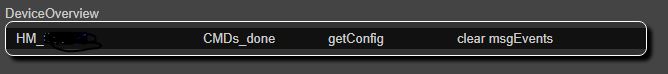
Ihr könnt die Kommunikation zwischen dem CUL und dem Device beobachten. Wieder unter CUL_HM sollte Euer Device nun vollständig definiert sein.
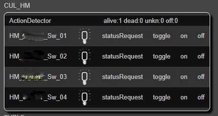
Mit einem Klick auf on / off schaltet ihr die Ausgänge! Wer möchte kann jetzt noch die Devices mit der Sprachsteuerung verbinden. Fertig!
How do I build a HomeMatic Actor?
- Buy a Arduino Nano, CC1101 and a relay board
- Wire the part accordingly (see plan below)
- Flash AsksinPP on your Arduino
- Pair it with FHEM or the HomeMatic CCU
Motivation
A HomeMatic actor is the counterpart to the CUL 868 and can be built just as cheaply and easily. The actuator supports AES encryption. There are various sketches that can be loaded onto the actuator. Four 5V relays for switching 220V can be connected to the module.
I have already built several of the actors and in the meantime had a small circuit board built in China, with which the assembly is much faster. If you are interested, feel free to contact me.
Used material
With the Arduino you have to make sure again that it has a real FTDI chip to avoid trouble and no CH340. If you build several of these actuators, you can also buy Pro Minis and flash them with a programmer.
Part
Arduino Nano FT232RL withUSB Kabel (Amazon, Aliexpress)*
CC1101 868 Mhz (Amazon, Aliexpress)*
Relais Board
(Note: As an Amazon affiliate, I earn from qualifying sales).
ArduinoCC1101VCC 3.3vVDDPIN GNDGNDnicht verbundenGDO2PIN D02GDO0PIN D10CSn (SS) (ggfs über 4k7 Widerstand mit 10k gegen GND)PIN D11SI (MOSI) (ggfs über 4k7 Widerstand mit 10k gegen GND)PIN D12SO (MISO)PIN D13SCK (ggfs über 4k7 Widerstand mit 10k gegen GND)
If you want to spare the CC1101, you can also install resistors to convert from 5V to 3.3V. For this you use 10k and 4k7 resistors. The alternative is to use a 3.3v Arduino, so Arduino and CC1101 have the same voltage level. Enclosed the circuit diagram for clarification.
Software
For the fourfold actor I use AsksinPP which is integrated into the Arduino as a library. I like AsksinPP especially the encryption. How we activate the encryption AES, I will show you in another article.
There are several examples in the library, so we concentrate on the fourfold actor and edit the file HM-LC-SWX-SM.
Device ID und Serial
We are looking for the following lines in the relatively short code.
// define all device properties
const struct DeviceInfo PROGMEM devinfo = {
{0x12,0x34,0x56}, // Device ID
"papa000000", // Device Serial
{HM_LC_SW4_SM}, // Device Model
0x16, // Firmware Version
as::DeviceType::Switch, // Device Type
{0x01,0x00} // Info Bytes
};
Define your device ID
{0x12,0x34,0x56}, // Device IDas well as your serial ID
"papa000000", // Device Serial
Relay PINs
Finally we define our relay PINs or just remember them. We can connect our Relay Breakout Board to these outputs.
#define RELAY1_PIN 5
#define RELAY2_PIN 6
#define RELAY3_PIN 7
#define RELAY4_PIN 3
Upload Softare
Now we are ready to compile and upload the code. We connect our Arduino with the PC and pay attention to the correct COM port. Then we compile the software and upload it to the Arduino.
Pairing
In principle we can pair the actor with a Homematic CCU. In my case we pair it with FHEM. For this we switch to our FHEM frontend. We enter into the command field
attr CUL1 hmPairForSec 600
to switch the CUL into pairing mode.
Now we have 10 minutes to pair our actor. We open the Serial Monitor of the Arduino with 57600 Baud and the Event Monitor (bottom left) of FHEM.
Then we connect PIN8 of the Arduino with GND for about 5 seconds. You should now be able to observe the communication between the CUL and the actuator in the serial monitor. If not, you can repeat the process as often as you like. After successful pairing you will see a new tab called CUL_HM in FHEM, which you open.
You get the Screen Device Overview. To make sure that all information has been transferred, click on getConfig
You can watch the communication between the CUL and the Device. Again under CUL_HM your device should now be fully defined.
Clicking the switch on / off will trigger the outputs! If you want, you can now connect the devices with the voice control. Done!
*Affiliate Links

Eine Antwort zu „Selbstbau HomeMatic Schaltaktor HM_LC_SW4_SM“
[…] Selbstbau HomeMatic Schaltaktor HM_LC_SW4_SM […]