
Click here for English version
Wie verbinde ich ein NodeMCU ESP8266 ESPEasy mit FHEM ohne zu löten?
- ESPEasy auf das NodeMCU ESP8266 flashen
- NodeMCU ESP8266 konfigurieren
- FHEM einrichten und Schalter anlegen lassen
- Testen
Ein NodeMCU ESP8266 ist vergleichbar mit einem Arduino mit integriertem WLAN Funkmodul (ESP8266). Die Integration in FHEM ist sehr einfach und schnell zu bewerkstelligen. An das NodeMCU lassen sich eine große Zahl von Sensoren anschließen, von denen sehr viele standardmäßig in der Software enthalten sind. Außerdem können einfache Aktoren wie Relais angeschlossen werden.
Hardware
NodeMCU ESP8266 (Amazon, Aliexpress)*
ESPEasy auf das NodeMCU ESP8266 flashen
Zunächst installieren wir uns den dementsprechenden Treiber für das NodeMCU. Ich habe ein NodeMCU mit einem CP2102 gekauft, da dieser sich auch unter Windows flashen läßt und ich nicht die Problematik eines CH340 habe. Der benötigte Treiber für den CP2102 bekommt man zb bei silabs und läßt sich ganz normal installieren.
Danach laden uns unter https://github.com/letscontrolit/ESPEasy/releases die aktuelle Version von ESPEasy auf den PC und entpacken sie. Wir verbinden unseren NodeMCU mit einem USB Port und starten den ESP.Easy.Flasher. Dann selektieren wir das aktuelle ESP Image, in meinem Fall das ESP_Easy_mega-20190202_normal_ESP8266_4096.bin und drücken Flash ESP Easy FW.

NodeMCU ESP8266 konfigurieren
Der ESP8266 macht nach dem Flashen und Neustart einen Access Point auf, d.h. wir können uns das Smartphone mit dem WLAN des NodeMCU verbinden. Der Access Point heißt in meinem Fall ESP_Easy_0 und kann durch Scannen des WLAN gefunden werden. Das voreingestellte Passwort ist configesp.

Danach öffnet sich automatisch ein Dialog der den ESP8266 mit dem WLAN des Heimnetzes verbindet. Falls der Dialog nicht startet, öffnen wir in unserem Browser die Seite 192.168.4.1. Wir wählen unser Heimnetz aus und verraten dem ESP8266 das Passwort.

Danach startet sich der NodeMCU neu und kann nicht mehr mittels Access Point erreicht werden. Er verbindet sich nach dem Neustart direkt mit dem WLAN.

Jetzt können wir den ESP8266 konfigurieren. Wir loggen uns mit unserem PC zunächst auf unserem Router ein und suchen die IP welche der Router an den ESP8266 vergeben hat. Diese geben wir in unserem Browser ein und es erscheint die Konfigurationsseite des NodeMCU.
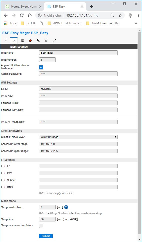
Wir öffnen den Reiter „Main Settings“ um das Board zu konfigurieren. Hier können wir einen eindeutigen Namen für den ESP vergeben. Unter SSID und WPA Key können wir unser WLAN Heimnetz konfigurieren.
Sollten wir mehrere ESPs am Laufen haben, achten wir darauf, daß wir für jeden ESP eine eindeutige Unit Nummer zwischen 1 und 31 vergeben.
Wichtig ist, den Access IP Lower und Access IP Upper so einzustellen, daß nur unsere internen Rechner auf den ESP zugreifen können.
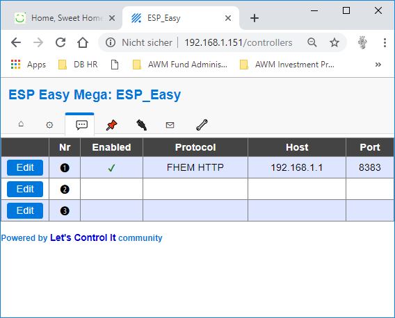
Unter dem Reiter „Controllers“ können wir die Kommunikation mit FHEM aufsetzen. Ganz wichtig ist bei dem Protocol FHEM HTTP auszuwählen, damit unser ESP auch mit FHEM kommunizieren kann. Die Controller IP ist die IP des Servers auf dem FHEM läuft. Den Controller Port setzen wir auf 8383 und klicken auf die Tick Box bei Enabled.
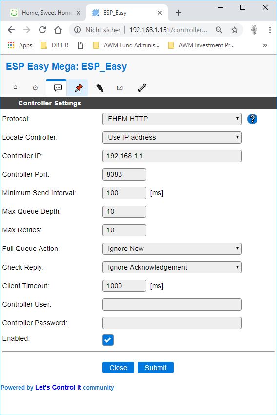
Und so sieht die Seite nach der Definition des Protokolls aus.
Dann wechseln wir in den Reiter „Devices“. Hier können wir unsere Aktoren und Sensoren definieren. In unserem Beispiel definieren wir einige digitale Ausgänge und Eingänge. Dabei ist zu beachten, daß nicht jeder Port als Ausgang oder Eingang nutzbar ist. Alle Eingänge bis auf D0 haben einen internen „Pull-Up“ aber ich habe festgestellt, daß mein Board abstürzt wenn ich D3 als Eingang verwende. Daneben werden beim Bootvorgang einige PINs getriggert, was zu ungewünschten Reaktionen führen kann, wenn daran Aktoren angeschlossen sind.
Wir definieren einen Digital Out um zum Beispiel ein Relais zu schalten, indem wir folgende Parameter setzen.
Name: SW1
Enabled: check
Inverse Logic: check
GPIO: 12
Switch Type: Switch
Send to Controller: check
Interval: 60
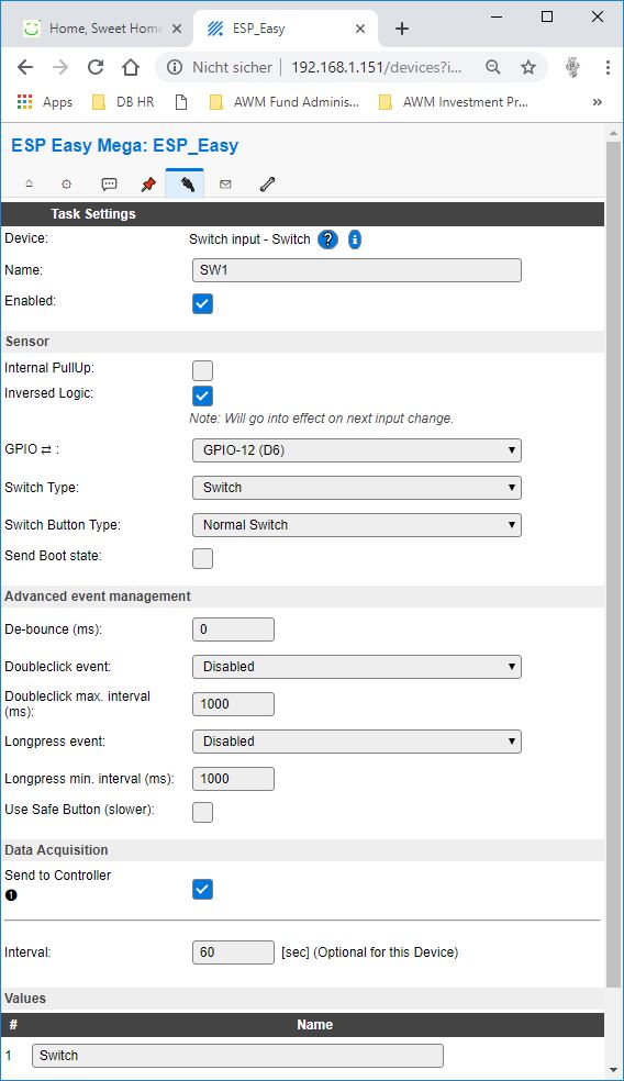
Auf diese Art und Weise wird alle 60 Sekunden der Status des switches bestätigt. Mein Relais ansteuern zu können, musste ich den Schalter invertieren. Je nach Anwendung kann das variieren.
Dann können wir noch ein „Digital In“ definieren:
Name: SW5
Internal Pullup: check
GPIO: 2
Switch Type: Switch
Send Boot State: check
Send to Controller: check
Interval: 60
Achtet darauf, daß der NodeMCU beim Digital In maximal 3.3v verträgt.
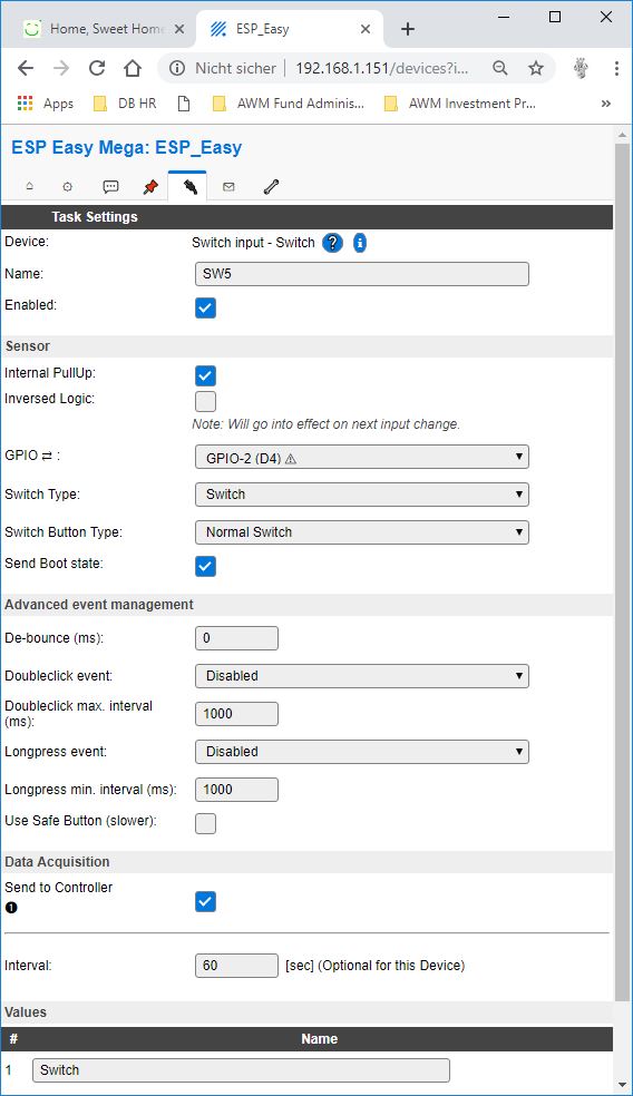
Bei jeder Änderung des Schaltzustandes wird ein Update an FHEM gesandt, spätestens alle 60 Sekunden.
Um einen permanenten Status Update über den Zustand des ESPs zu erhalten definieren wir noch einen Kanal um einige interne Parameter an FHEM zu übertragen.
Indicator 1: Uptime
Indicator 2: WIFI RSS
Indicator 3: Input VCC
Indicator 4: System Load

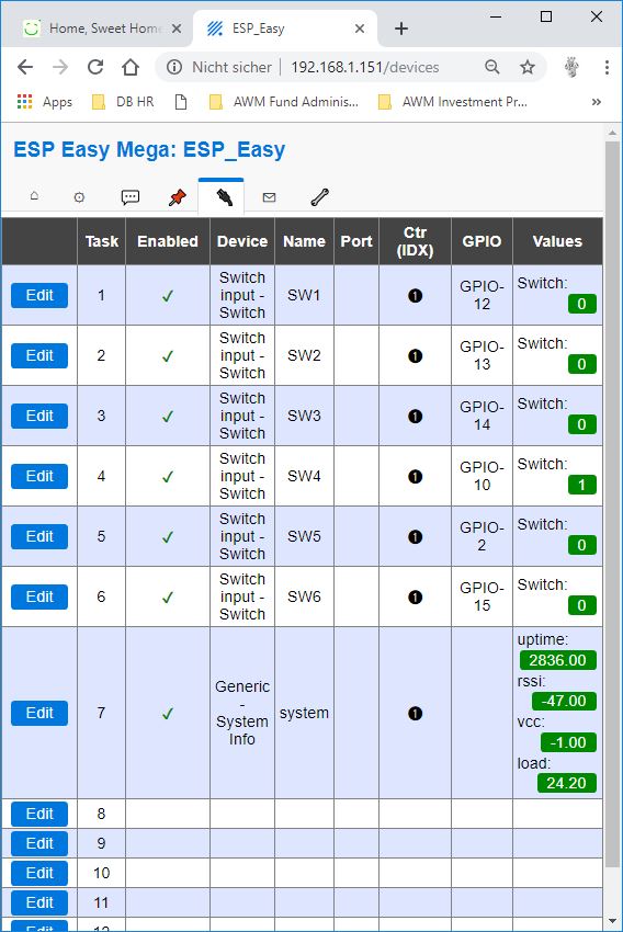
Insgesamt habe ich die folgenden Devices definiert. Alle Devices laufen bei mir stabil, es kommt keinerlei Absturz oder ähnliches.
FHEM einrichten und Schalter anlegen lassen
In dem Kommandofeld von FHEM geben wir
define espBridge ESPEasy bridge 8383
ein. Damit ist FHEM schon fertig konfiguriert. Es sollte auch schon der Status des ESP8266 erscheinen.
Wir können nun unsere angelegten Schalter mit einer kleinen Litze kurz mit GND und auf 3.3V verbinden. Damit meldet der ESP8266 einen neuen Schaltzustand und das Gerät wird automatisch in FHEM angelegt. Alternativ wird das Gerät automatisch angelegt, wenn der NodeMCU ein periodisches Update zum Schaltzustand schickt.
In meinem Fall musste ich den Schaltzustand invertieren. Bei mir ist ein off ein on und umgekehrt. Deswegen habe ich die Schalter folgendermaßen konfiguriert:
attr eventMap /gpio 12 on:off/gpio 12 off:on/status gpio 12:check/
Und am Schluss setzen wir noch Icons für die Schaltzustände.
attr devStateIcon*.off:FS20.off .*on:FS20.on :FS20.on :FS20.on

How do I connect a NodeMCU ESP8266 ESPEasy to FHEM without soldering?
- Flash ESPEasy to the NodeMCU ESP8266
- Configuring NodeMCU ESP8266
- Set up FHEM and have switches created
- testing
A NodeMCU ESP8266 is comparable to an Arduino with integrated WLAN radio module (ESP8266). Integration into FHEM is very easy and fast. A large number of sensors can be connected to the NodeMCU, many of which are included in the software as standard. Simple actuators such as relays can also be connected.
Hardware
NodeMCU ESP8266 (Amazon, Aliexpress)*
Flash ESPEasy to the NodeMCU ESP8266
First we install the corresponding driver for the NodeMCU. I bought a NodeMCU with a CP2102, because it flashes under Windows and I don’t have the problems of a CH340. The required driver for the CP2102 is available at silabs and can be installed normally.
Then download the current version of ESPEasy to your PC at https://github.com/letscontrolit/ESPEasy/releases and unpack it. We connect our NodeMCU with a USB port and start the ESP.Easy.Flasher. Then we select the current ESP image, in my case ESP_Easy_mega-20190202_normal_ESP8266_4096.bin and press Flash ESP Easy FW.
Configuration of the NodeMCU ESP8266
The ESP8266 opens an access point after flashing and restarting, i.e. we can connect the smartphone to the WLAN of the NodeMCU. The access point in my case is called ESP_Easy_0 and can be found by scanning the WLAN. The default password is configesp.
Then a dialog opens automatically which connects the ESP8266 with the WLAN of the home network. If the dialog does not start, we open in our browser the page 192.168.4.1. We select our home network and tell the ESP8266 the password.
Then the NodeMCU restarts and can no longer be reached via Access Point. After restarting, it connects directly to the WLAN.
Now we can configure the ESP8266. We log in with our PC on our router and look for the IP which the router has assigned to the ESP8266. We enter these in our browser and the configuration page of the NodeMCU appears.
We open the tab „Main Settings“ to configure the board. Here we can assign a unique name for the ESP. Under SSID and WPA Key we can configure our WLAN home network.
If we have several ESPs running, we make sure that we assign a unique unit number between 1 and 31 for each ESP.
It is important to set the Access IP Lower and Access IP Upper so that only our internal computers can access the ESP.
Under the tab „Controllers“ we can set up the communication with FHEM. It is very important to select FHEM HTTP for the protocol so that our ESP can also communicate with FHEM. The Controller IP is the IP of the server running FHEM. We set the controller port to 8383 and click on the tick box at Enabled.
And this is the page after the definition of the protocol.
Then we switch to the „Devices“ tab. Here we can define our actuators and sensors. In our example we define some digital outputs and inputs. Please note that not every port can be used as output or input. All inputs except D0 have an internal pull-up but I noticed that my board crashes when I use D3 as input. In addition, some PINs are triggered during the boot process, which can lead to unwanted reactions if actuators are connected to them.
We define a Digital Out to switch a relay, for example, by setting the following parameters.
Name: SW1
Enabled: check
Inverse Logic: check
GPIO: 12
Switch Type: Switch
Send to Controller: check
Interval: 60
As a result the status of the switch is confirmed every 60 seconds. To control my relay, I had to invert the switch. This can vary depending on the application.
Then we can define a „Digital In“:
Name: SW5
Internal Pullup: check
GPIO: 2
Switch Type: Switch
Send Boot State: check
Send to Controller: check
Interval: 60
Make sure that the NodeMCU can handle a maximum of 3.3v with Digital In.
Each time the switching state is changed, an update is sent to FHEM, at the latest every 60 seconds.
To get a permanent status update about the state of the ESP we define another channel to transfer some internal parameters to FHEM.
Indicator 1: Uptime
Indicator 2: WIFI RSS
Indicator 3: Input VCC
Indicator 4: System Load
Altogether I have defined the following devices. All Devices run stable with me, it comes no crash or similar.
Set up FHEM and setup switches
In the command field of FHEM we enter
define espBridge ESPEasy bridge 8383
By that FHEM is already configured. The status of the ESP8266 should already appear.
Now we can connect our switches with a small wire briefly to GND and to 3.3V. The ESP8266 reports a new switching state and the device is automatically set up in FHEM. Alternatively, the device is automatically created when the NodeMCU sends a periodic update to the switching state.
In my case I had to invert the switching state. In my case an off is an on and vice versa. Therefore I configured the switches as follows:
attr eventMap /gpio 12 on:off/gpio 12 off:on/status gpio 12:check/
And at the end we set icons for the switching states.
attr devStateIcon*.off:FS20.off .*on:FS20.on :FS20.on :FS20.on
